For creating a perforated panel Revit is a great option. Especially with Dynamo Script for Revit has never been easier. The power of Dynamo raised Revit to a new level. However, many of you still did not have a chance to work with Dynamo or rather find it very difficult to understand. Most designers are abstract thinkers and they do not acquire coding skills to perform complex design and modeling.
In today’s post, we are going to discuss how we can bridge this issue. If you are interested in modeling and designing Perforated Panels in Revit, the Integrated BIM team makes it even easier for you. Simply get the Dynamo script for Revit and follow the steps in this article or in the video at the bottom of the page.
Fill Out the Form & Get the Dynamo Script For Revit in Your Inbox
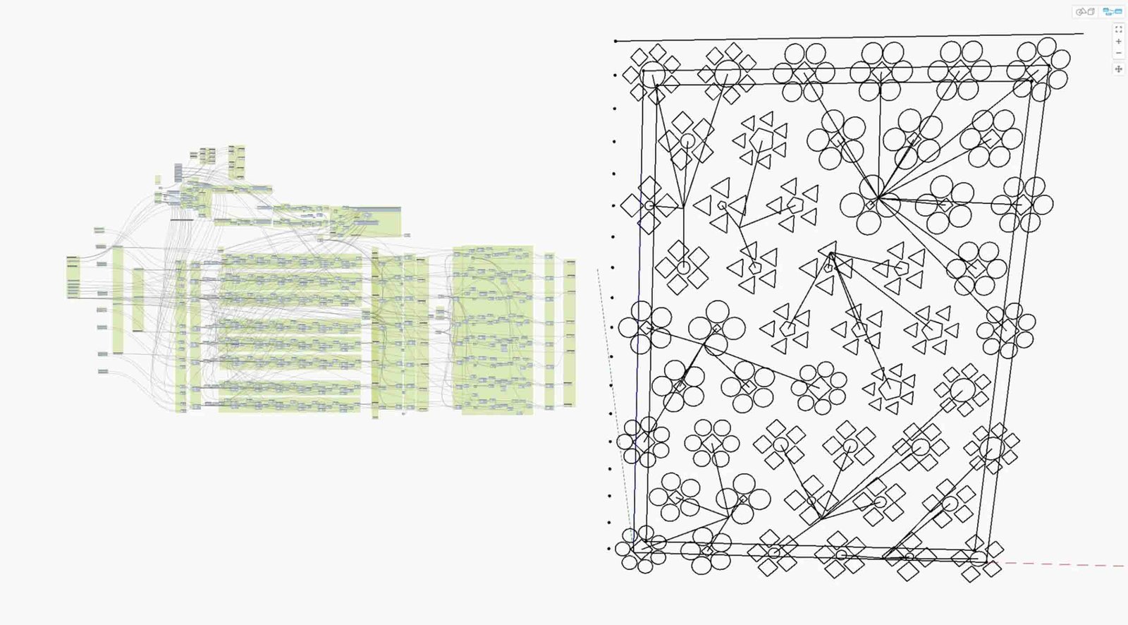
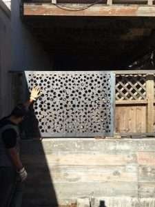
JUST BEFORE doing that… Hold on for a second and take a look at these results:



STEP 1
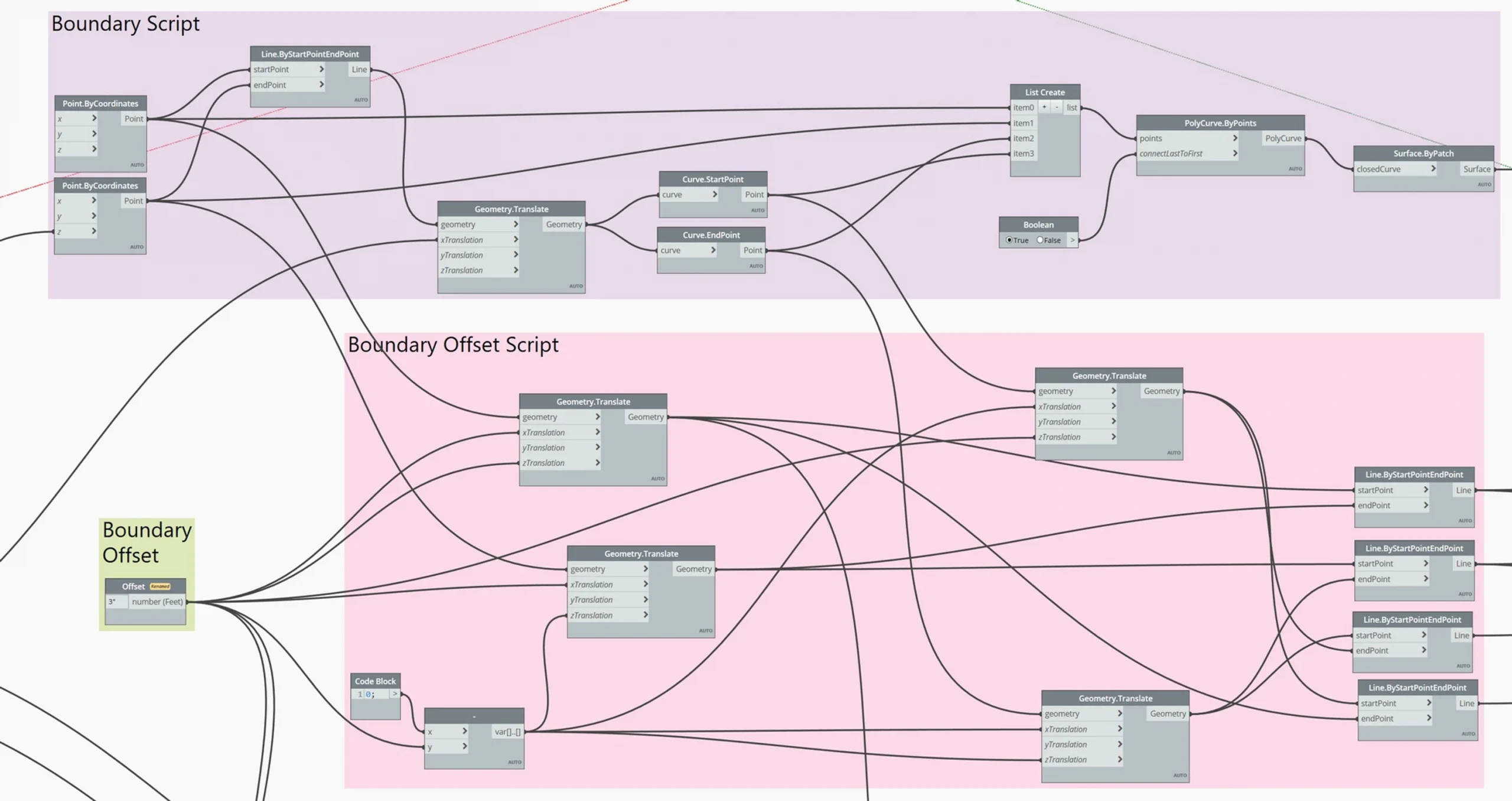
Let’s start with an origin point and create the boundary out of that. The idea here is to create a panel size that can be controlled through dimensions that can be manually entered or with a slider. Once the enclosed boundary is created, we can now generate a surface out of that which acts as the panel.
STEP 2
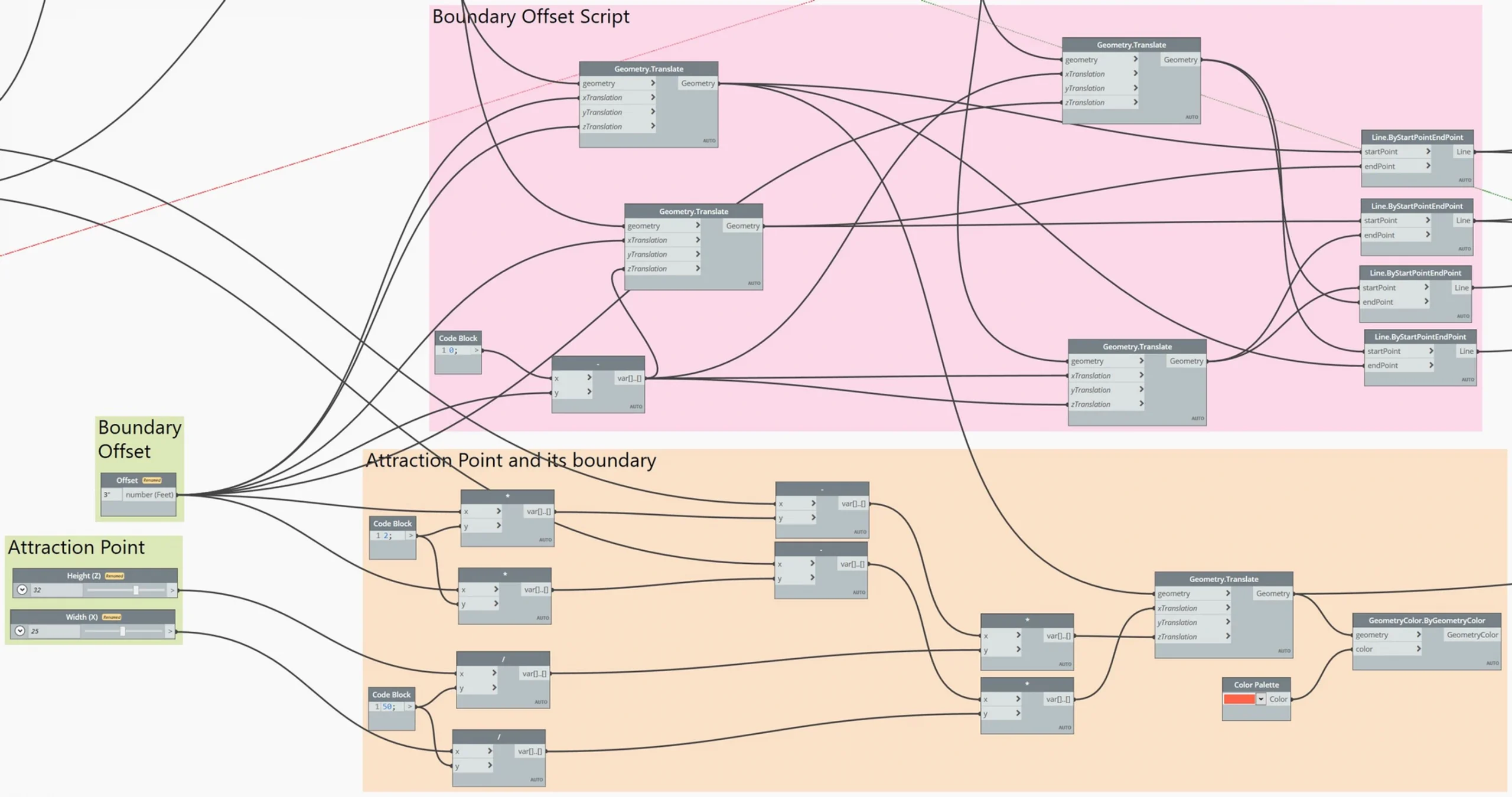
An offset boundary is always a good idea. This can be used to control the tolerance for laser cutting or 3D printing and if no boundary is required then it can be easily set to “0”.
STEP 3
Now, it is time to create a grid of points. In this script, we are aiming for a checkered pattern in order to get an interesting design for the perforated panels in Revit rather than a modular grid system. You can simply use an odd numbering system and remove every second n value (for instance, if you have 4 rows of 1 – 5 (odd number), if you remove 1, 3 and 5 in the first row, in the second row it will remove 2 and 4. Then, in the third it will repeat itself 1, 3…)
STEP 4
An attraction point is required if we want to take and control the ownership of the grid of points since those points will act as the center to generate all the shapes and forms.
STEP 5
Diameter lengths of the shapes and forms are created through a formula based on the distance between the grid points vertically, horizontally, and diagonally. In this case, a 45-degree triangle formula is being used. The output of the formula is considered as the max. radius and the minimum radius is an option (or depending on the laser cut and/or 3D printing systems). A node is being used to convert the distance between the attraction point to each point in the grid and a ratio of value is assigned based on its maximum and minimum radius.

STEP 6
The last step is to take the Dynamo script for Revit into Revit and generate a 3D panel with perforations. Therefore, once the grid of shapes is subtracted from the surface, we can generate a form by assigning a thickness.
If this article and our Dynamo script for Revit are helpful to you, consider subscribing to our Newsletter. Be the first to receive helpful BIM and AEC content with real examples from our practice, and lots of free useful resources.
After you’ve read our step-by-step guide for creating a perforated panel with Revit, you are now ready to do it yourself.
Are you interested in broadening your horizons and enhancing your abilities in Revit?
Our very own Knowledge Base is a rich source of valuable information that can assist you in achieving precisely that! Sign up today to open up a realm of knowledge and bring your skills to greater heights.


